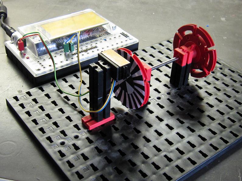
spursucher as incremental encoder

Hochgeladen am 21.5.2009, 12:10 von Ad. 1 / 1
Schlagworte: spursucher, segmentscheibe, quadrature, incremental, encoder.
test configuration with two different resolutions
Stefan Falk (21.5.2009, 13:07:51)
This is a great idea! Does it work?
Regards, Stefan
Ad (21.5.2009, 14:03:37)
Yes I posted the robopro program in the download area. As usual the relatively low sample frequency is the main limitation. But when you turn it slowly it is accurate even with 36 segments.
MisterWho (21.5.2009, 14:32:20)
Is there a big LCD in your Interface?
schnaggels (21.5.2009, 17:38:01)
Why didn’t I get this idea? Sounds too logic maybe :)
BTW, the color sensor works more stable for line tracking purposes in different situations then this sensor :)
It’s too pity not having a second fast counter. Maybe some of our community hardware gurus will find a way to re-use an existing input as a second one.
@MisterWho Yes, have a look here: http://www.ftcommunity.de/details.php?image_id=17130
Ad (21.5.2009, 20:22:27)
The hardware counter could be used if we do the conversion from quadrature to up/down count externally. I don’t think there are any more timers available but with extension modules anything is possible :)
@schnaggels: Thats good because, as a colour sensor it sucks.
It probably isn’t clear from the picture but with proper alignment you can determine the count direction and increase the resolution (see my robopro prog for an example on how to achieve this). For the segmentscheibe I used the excel sheet from Andreas Guerten, works a charm.
Ad (21.5.2009, 20:52:23)
The hardware counter could be used if we do the conversion from quadrature to up/down count externally. I don’t think there are any more timers available but with extension modules anything is possible :)
@schnaggels: Thats good because, as a colour sensor it sucks.
It probably isn’t clear from the picture but with proper alignment you can determine the count direction and increase the resolution (see my robopro prog for an example on how to achieve this). For the segmentscheibe I used the excel sheet from Andreas Guerten, works a charm.
niekerk (22.5.2009, 21:35:49)
Nice, Ad.
I’ve been thinking about using the [I]color[/I] sensor for odometry. But in a rather different way. I’d like to take advantage of the analogue nature of the sensor, and use an encoder disk with gray ramps. So in stead of the black and the white segments, you’d have segments containing a ramp or gradient from white to black. Even with a relatively low sample frequency you would have precise information on the distance traveled. In theory this would even work in both directions.
In practice, some calibration would be required. Also, I have not been able yet to create such analogue encoder disks. Postscript code for digital disks is plenty, but analogue none. Now if someone could help me out here …
Groeten, Paul
niekerk (22.5.2009, 21:41:23)
@Ad: when the low sampling frequency is the bottleneck, one solution would be to use the 1 msec timer tick in download mode to sample the input. Just an idea, I never got to actually do this myself.
Regards, Paul
Ad (23.5.2009, 17:09:17)
Hi Paul,
I was thinking about using the 1ms timer too. When I do everything in C that should not be a problem. If I want to interface to RoboPro it is more difficult. I could send messages to RoboPro (like a mouse) say every 20ms, but I don’t know if robopro can handle this amount of messages. BTW. I have a program (C++ Builder) that draws gradient disks and copies them to the clipboard (as bitmap). I can print them with ‘Paint’ at true size (72dpi).
Regards,
Ad
Ad (24.5.2009, 11:54:11)
@Paul: I tried you idea with the gradient disk and the colour sensor! At 1cm distance (60mm disk) I get a response from 32 to 304 (linear ramp gradient). Near the steep edge it requires about 60 degrees turn from the highest to the lowest response. So the response is not unique and an algorithm has to take that into account. There is no way for an algorithm to know whether it turns fast in one direction or slow in the other direction.
niekerk (25.5.2009, 23:53:59)
@Ad: OK! I agree. Your experiment shows that the Field of View (FOV) is quite big. Decreasing the distance between sensor and the disk should then improve the result. But you can´t get rid of it completely because the transmitter and the receiver are placed some 5 mm apart. Placing the sensor up right may also help a little, i.e., transmitter and receiver above each other.
Using two sensors may perhaps solve the problem, but that is not what I had in mind. Too bad!
Stefan Falk (26.5.2009, 00:03:49)
Might some lens help? Perhaps one of those of the old fischertechnik electro-mechanics program?
Regards, Stefan
Ad (26.5.2009, 10:21:45)
These are good ideas! I will play a bit more and see if I can improve the steepness of the edge without losing resolution in the other parts. But I think the problem is fundamental and should be resolved with a clever algorithm or better pattern. Using two colour sensor will definitely solve the problem. Using a sine pattern will give resolver like signals that should give unambiguous position information. I will try this as well.
schnaggels (12.6.2009, 09:28:24)
Fast counter within RoboPro now also possible on RoboIF!!! http://www.ftcommunity.de/wiki.php?action=show&topic_id=33