Taster-Stapel und Kabelsalat
Hochgeladen am 17.4.2018, 22:07 von hamlet. 14 / 17
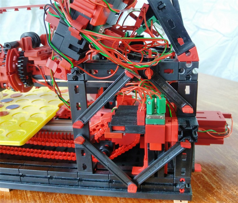
Bei drei Encoder-Motoren verbleiben zwei O-Ausgänge. In der Nullposition des Linear-Vorschubs werden die beiden Ausgänge von den Magneten auf den xs-Motors des Spenders und die Versorgung des Farbsensors umgeschaltet. Die Stapelbarkeit bei den Tastern vorzusehen, war schon eine geniale Idee von fischertechnik.
Robot I/O: M1/C1/I1: Encoder motor driving the straight axis of the board (d position) M2/C2/I2: Encoder motor that rotates the board (phi position) M3/C3/I3: Encoder motor driving the planetary magnet token turner O7/O8: If M1 not in zero position: O7/O8 drives the turner’s electromagnets If M1 in zero position O7 drives the token dispenser’s crank xs motor and O8 powers the ft color sensor I5: Monitors the 9V supply. Used to ensure U>8V for the magnet’s token handover. And also helped to detect a defect magnet 15Ohm instead of 46Ohm. I6: Player’s confirmation button I7: Color sensor input I8: Dispenser crank drive end position switch