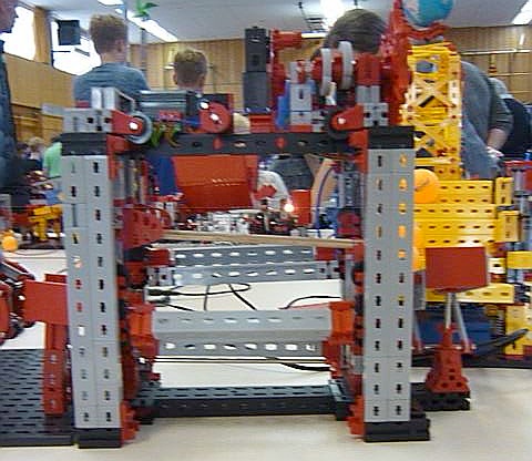
Hebewerk - Seitenansicht
Hochgeladen am 4.2.2018, 20:58 von H.A.R.R.Y. 1 / 4
Schlagworte: Gemeinschaftsprojekt, Tischtennisballmaschine, Hebewerk, Pendelaufzug.
Unten werden die Bälle durchgeschleust, obendrauf thront die Steuerung.
Wie in einem der grossen Schiffshebewerke auch, gibt es zwei gekoppelte Tröge die abwechselnd auf und ab fahren. Die Kopplung hebt die Eigengewichte der Tröge effektiv auf und der Antrieb muss lediglich die Reibungsarbeit aufbringen. Hier stimmt das nicht ganz, aber das Ungleichgewicht hält sich mit 3 Bällen in überschaubaren Grenzen.
Der jeweils unten wartende Trog kippt die mittlere Wanne, auf der bis zu 3 Bälle warten können, zu sich und so steigen die Bälle in den Trog ein. Nachzügler biegen direkt ab. Der jeweils oben wartende Trog wird zur Mitte hin gekippt und die Bälle steigen auf die Auslaufschienen (Holzstäbe) um.
Die Steuerung sorgt nun dafür, dass in regelmäßigen Zeitintervallen ein Trog hochfährt während der andere absinkt. Endlagetaster begrenzen die Hubbewegung auf den zulässigen Bereich.
Der Aufzugsockel misst über Alles 300 x 150 mm². Die Abmessungen sind speziell auf eine undokumentierte Eigenschaft der TTB-Module des ftc-Gemeinschaftsprojekts ausgelegt (https://www.ftcommunity.de/wiki.php?action=show&topic_id=41) und deswegen konnte das Hebewerk letztes Jahr in Dreieich ‘mitspielen’.
Ja, die Bildqualität ist nicht berauschend. Das hier ist leider das Beste was mit allen Tricks aus dem Rohmaterial herauszuholen war.
=====================================
Below the balls are handled, on top the control mechanism resides.
Like in some of the big boat lifts there are 2 coupled troughs moving up and down mutually. The coupling effectively nulls out the troughs weight just loading friction losses to the drive. Here this is just not completely true but the weight of just 3 balls does not put much burden to the drive motor.
The trough at the bottom tilts the entry well in the middle over and so the balls get on the trough. Up to 3 balls can wait for the trough to arrive. Balls arriving while the trough is at its lower rest roll directly onto the trough. At the top the trough itself is tilted toward the middle. Thus the balls roll onto the wood rails and then leave the lift.
The movement of the trough is triggered by the control mechanism. End position switches stop the movement at the right moment.
The lift’s base measures just 300 x 150mm². The measures are well tuned to an undocumented property of the community project (https://www.ftcommunity.de/wiki.php?action=show&topic_id=42). For this reason this lift succesfully fitted into the contraption at Dreieich last year.
Please excuse the poor picture quality. It is the best that could be achieved from the raw material playing all available tricks.
Maybe this clip aids in understanding how things work: https://youtu.be/ZYH144aMy8Y