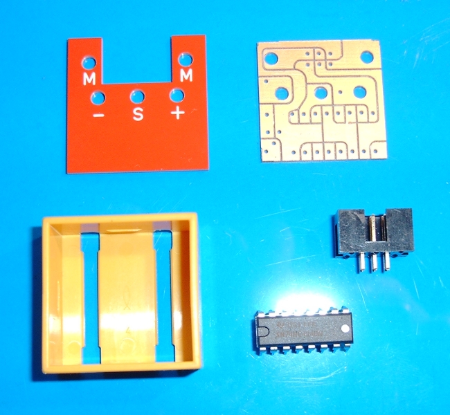
Die wichtigsten Einzelteile
Hochgeladen am 13.4.2009, 20:49 von TST. 1 / 4
Nun bin ich auch in den Elektronik Bereich eingestiegen. Ich habe mit Hilfe von DMDBT (hier noch mal DANKE) einen Impulswandler entworfen der die zu schnellen Impulse des Encoders der an den Maxon Motoren 138062 sitzt teilt. Der Encoder liefert ein Signal mit einer Frequenz von ca 1950 Hz. Das ist für das Interface natürlich viel zu schnell. Der Binärzähler 74HC4040N teilt dieses Signal durch 64. Somit erhält man ein Signal was das Interface verarbeiten kann. Die Motoren lassen sich somit super für Positionerrungen nutzen. Hier die wichtigsten Bestandteile. Es fehlen im Bild noch ein Spannungswandler, eine Diode sowie die Steckerhülsen.
niekerk (13.4.2009, 21:52:38)
Well done, looks great. This should work fine for the RoboInterface. But for the new TX controller, division by 2 would be more appropriate, since it handles signals up to 1 kHz. So in order to be future proof, you would need to have two outputs: div64 for the RoboInterface as well as div2 for the new TX controller.
Paul
TST (13.4.2009, 23:14:29)
Hallo Paul Wenn ich das Layout der Platine verändere ist ein Teilen durch 2 auch möglich. Da ich aber nur die Robo Interface besitze habe ich mich erst mal darauf konzentriert.
Udo2 (14.4.2009, 00:49:08)
Hallo Andreas, die Lösung mit einem Binärzähler die Impulszahl für das Robo Interface anzupassen ist interessant. Es bleiben 1950Hz / 64 * 60 = 1828 Impulse/min. Schafft das Interface das auch mit dem Impulstyp 0 -> 1 oder 1 -> 0 ? Gruss, Udo2
TST (14.4.2009, 20:33:44)
Hallo Udo
Ja das Inferface schafft es. Mit 0 -> 1 oder 1 -> 0 geht ab und zu ein Impulse verloren, am zuverlässigsten läuft er mit 0->1, das ist das Ding echt präzise.
Ad (16.4.2009, 19:35:40)
Hi Andreas,
Nice construction but electronically I suspect a small snag. This may become noticable when you change the motor direction and is caused by the divider. Suppose you turn the motor clockwise, the divider contains 0 and your software counter is also 0. Now suppose you stop the motor when the count reaches 100 (count only falling edges), the divider will contain an unknown number between 0 and 63, let’s assume it is 60. Now when you reverse the motor (counterclockwise) you would expect a rising edge after 60 encoder pulses but this is not the case because the divider still counts up, so instead you will have a falling edge after 4 encoder pulses. This will result in a small error that however will accumulate causing your software zero to drift away from the starting point. The remedy would be to use an up/down counter for the divider. The count direction has to be determined by the other encoder channel. On the Internet I found an IC that might be suitable (uPD4702) but I don’t know if it is easy to get. Otherwise we will have to make something in a GAL. Regards, Ad
schnaggels (22.4.2009, 10:52:50)
I think there a lot of logic ICs in DIL package with counting / dividing functions. Finding the rigth is the problem, will also have a look if I find time…
Thomas
Ad (22.4.2009, 11:07:54)
For this application I could even program a tiny avr (8 pin dip). Then we could even add some functions like hysteresis, programmable division ratio or I2C interface.
Ad
schnaggels (28.4.2009, 13:28:22)
Spoke with Andreas, the error shouldn’t be significant for use with ft positioning. I don’t 100% agree, have to test this by myself when I got these motors soon…
Ad (9.5.2009, 22:37:21)
I don’t have the motors (and don’t intend to buy them) but I did a simulation in excel. It turns out there is a random error (positive or negative) that accumulates (a random walk). The error only increases in back and forth movements. Depending on the actual movements the error may stay close to zero or may increase rapidly, this is unpredictable. The effect it is that after a lot of movements your zero postion is not what you expect it to be, you may blame this on missed pulses or glitches but the real cause is a design flaw.